
Ladder logic programming is a graphical programming language used primarily in industrial automation systems to program a PLC (Programmable Logic Controller). It is a fast and simple way of creating logic expressions for a PLC to automate repetitive machine tasks.
Ladder logic programming uses a standardized set of symbols and notation to represent the various components and functions. Each rung of the ladder diagram consists of a series of contacts and coils, with the contacts determining the conditions under which the coils are energized or de-energized. The program is executed by scanning each rung in sequence, evaluating the conditions set by the contacts, and updating the state of the coils accordingly.
Ladder logic programming is easy to learn and mimics electrical circuits, making it easy to troubleshoot once deployed. Best practices for ladder logic programming include organizing and structuring the program, implementing error handling and diagnostics, using modular and reusable code, testing and validating the program, and documenting the program.
Ladder logic programs are used in a multitude of industrial automation applications, such as material handling conveyor systems, pallet packing and strapping, ball mill lubrication systems, logistics package conveying and sorting, cement batching, and beverage bottling and labeling.
Components of a Ladder Diagram
Imagine a ladder with vertical rails on each side connected by horizontal rungs. These rungs represent the logic conditions that control the outputs.
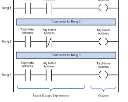
- Rails: The vertical lines on both sides represent the power flow. Think of them as the positive and negative terminals of a battery.
- Rungs: Each horizontal line represents a single logic expression. It’s like a mini-circuit within the larger program.
- Contacts: These symbols represent inputs (sensors, switches) and their states. They can be:
Normally Open (NO): The contact is open when the input is inactive and closes to complete the circuit when the input is active.
Normally Closed (NC): The opposite of NO. The contact is closed when the input is inactive and opens to break the circuit when the input is active.
- Coils: These symbols represent outputs (relays, motors) controlled by the logic on the rung. When all the conditions on a rung are met, the coil is energized, activating the output.
Logic Flow
The PLC scans the ladder diagram rung by rung, from left to right.
- Input check: The PLC reads the state of each input (sensor, switch) connected to the contacts on the rung.
- Condition evaluation: Based on the type of contact (NO/NC) and its state, the PLC determines if the condition on that contact is true or false.
- Output activation: If all the conditions on a rung are true (contacts are closed in the correct configuration), the coil on that rung is energized. This activates the corresponding output (motor, relay).
- Continuous scan: The PLC repeats this process continuously, scanning all rungs in the program one after another.
Common Instructions
While basic logic like AND, OR, and NOT can be achieved using contact combinations, ladder logic also includes special instructions for more complex control:
AND Function
The AND function examines multiple PLC inputs and has one resulting output. If we translate an AND function into a ladder diagram we can express it symbolically in the form of two PLC inputs A and B using normally open (NO) contacts and a PLC output Y using a relay coil. They are all connected in line, just like a series connection in an electric circuit.
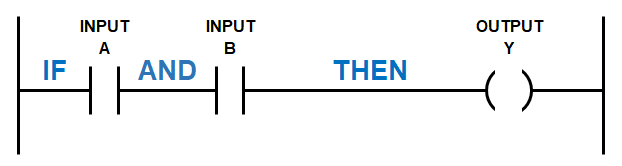
We can write out the logic expression above as IF A AND B THEN Y. The AND function examines if all the PLC inputs are TRUE, then the corresponding result is also TRUE. However, if any one of the PLC inputs is FALSE then the corresponding result is also FALSE.
Or Function
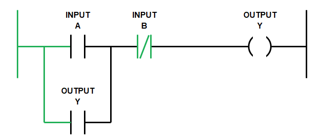
The OR function examines multiple PLC inputs and has one resulting output. If we translate an OR function into a ladder diagram we can express it symbolically in the form of two PLC inputs A and B using normally open contacts (NO) and a PLC output Y using a relay coil.
The inputs are placed in the rung in what is known as a branch. This is the equivalent of a parallel connection in an electric circuit. The output is then connected in line with the rung.
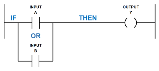
We can write out the logic expression above as IF A OR B THEN Y. The OR function examines if any of the PLC inputs are TRUE, and then the corresponding result is also TRUE. However, all the PLC inputs must be FALSE for the corresponding result is also FALSE.
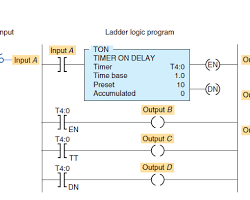
- Timers: These instructions trigger outputs after a preset time delay. Imagine a rung with a timer instruction and a coil. When the timer expires, the coil energizes, activating the output.
- Counters: These instructions count pulses from inputs and control outputs based on the count value. For example, a counter can be used to activate an output after a specific number of parts have been produced.
- Arithmetic operations: Some PLCs allow basic math operations like addition, subtraction, comparison, etc., within the ladder logic.
Applications
Ladder logic is widely used in industrial automation for various applications, including:
- Conveyor systems: Controlling the flow of materials based on sensors and buttons.

- Robotic arms: Sequencing movements and actions based on program logic.
- Machine safety: Implementing interlocks and emergency stops to prevent accidents.
- Data acquisition: Collecting and processing data from sensors for monitoring and analysis.
Conclusion
Ladder Logic opens the door to controlling machines and processes clearly and flexibly. It’s like a visual programming language, making it easy to learn and perfect for anyone entering the world of industrial automation. With practice and exploration, you can build complex control systems and turn your automation dreams into reality!

Fathima Sadina works as a Technical Associate at IIPD, where she dives into the world of Industrial Automation, focusing on PLC, SCADA, and VFD systems. With a keen passion for spreading know-how, she loves to craft engaging blog posts on a wide array of technical subjects.