Discover the ins and outs of understanding electrical wiring diagrams in industrial automation with this special article.
These diagrams are like maps that help us see how all the electrical parts fit together in different systems. They show us how to set up cables and things like switches, boards, sockets, and lights in buildings.
Whether you’re planning a new electrical system, fixing problems with old ones, or just doing upkeep, a good wiring diagram gives you a picture of how all the parts connect and work together.
Dive into this article to learn how to read wiring diagrams in industrial automation. It’s a skill that helps you understand complicated industrial processes better.
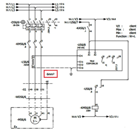
The Electrical Wiring Diagrams emphasize connections between elements of a circuit or system. The horizontal and vertical lines are used to represent the wires. Uses simplified pictorials that resemble circuit/system components.
Understanding basic wiring terminology and identifying the most common types of wire and cable will help when investigating wiring problems and when choosing the wiring for new installation and remodeling projects.
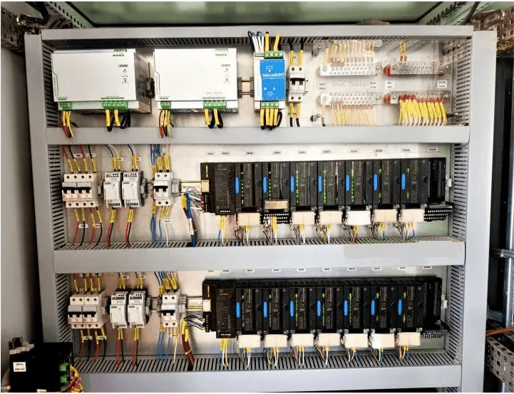
PLC WIRING
The PLC panel consists of the main breaker switch, bus bar, circuit breakers, relays, contactors, Programmable logic controllers, fuses, SMPS, terminal boards, utility sockets, and earthing points.
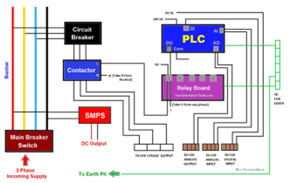
Main Breaker Switch
This is the point where the main power supply (3 phases) is connected (R, Y, B, N). It is this point that supplies power to all the components. Install the breaker in such a way that the wireman gets a free hand to do the wiring; because any lag in it can damage the whole system.
Busbar
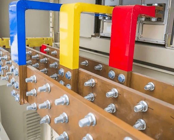
In the next step, connect the output of the main breaker switch to the busbar. The bus bar provides proper electrical distribution. So, if there are many components in the panel that require a single-phase supply or three-phase supply, then the bus bar is the most efficient step to do it. Distribute all the points from here to the ones which require single-phase or three-phase supply.
This will help you with easy and efficient power management. It’s not possible to loop the three-phase wires to different components, as it is the wrong practice and can damage the wiring or the whole electrical panel in total.
Circuit Breakers
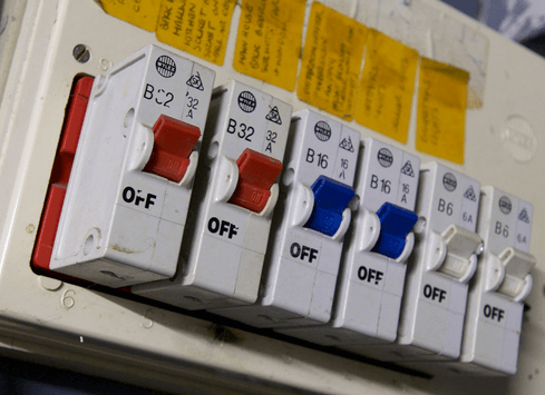
Now, suppose there are three circuit breakers in the panel. Connect the three-phase wires from the bus bar to each of the circuit breaker inputs. Individual circuit breakers will power individual contactors connected to their output. This will give proper output control to the contractors. Because contactors have a control circuit that is controlled by the PLC; thus, giving individual three-phase control too will give proper electrical control over the final output
SMPS
Now, from the bus bar, connect one point to the SMPS. This will power it up and give DC output to the cabinet. If the current rating of SMPS is higher, then you can use a distribution terminal board too for DC supply. This will properly segregate the DC supply to all the components requiring it. From this, power the PLC.
Now, after this, we will see how to wire the PLC IOs.
Digital Inputs
Firstly, take digital inputs. According to sink or source wiring, connect either 24V or 0V to the PLC common. So, for example, if the common is 24V, connect 0V to all the respective PLC field inputs in the terminal board. As one board has two pins, one will be used to provide 0V and the other will be connected to PLC digital input. For safety, many use fuse terminal boards. This provides additional safety to the field devices.
Digital Outputs
Then, coming to digital outputs, the same sink and source theory applies to it. So, for example, if the common is 24V, connect 0V and PLC digital outputs to all the relays (the relay has two pins, so one pin will be 0V and the other pin will be PLC digital output). According to the output you want at the relay output (DC or AC), connect the wiring accordingly.
For example, if the relay output required is 230V AC, connect the line wire to the common and connect the NO wire to the contactor’s line input.
Connect the neutral wire to the contactor’s neutral input and thus, the circuit is complete. Now, whenever the relay turns on, that particular contactor will turn on and if its MCB is on, then the three-phase supply will be passed on to the final output.
Analog Inputs and Outputs
Now, analog input and analog outputs will be directly routed through terminal boards concerning PLC. If possible, use fused terminal boards for additional safety.
Terminal Boards
Coming back to the contactors, the output is connected to terminal boards where you can connect your final output.
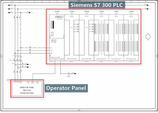
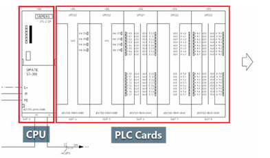
READING PLC WIRING DIAGRAM
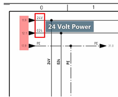
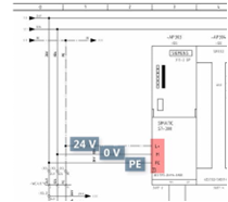
The 24 volts, zero volts, and earthing are respectively connected to L+, M, and PE terminals on the PLC CPU.
The arrow on the left-hand side of the PLC rack means that the rack will be continued on the next page of the PLC wiring diagram.
PROFIBUS Communication with PLC
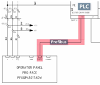
The operator panel is communicating with the PLC directly via the MPI port of the CPU using a PROFIBUS cable.
The WCDP5 cable is also a PROFIBUS cable as it’s connected to the DP port of the CPU.
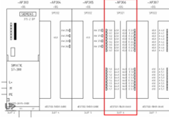
PLC ANALOG OUTPUT CARD DIAGRAM
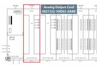
In the PLC wiring diagram, you see that each channel of this analog output card is dedicated to a single device.
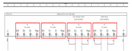
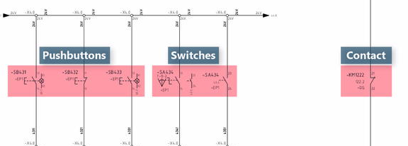
PLC DIGITAL INPUT CARD DIAGRAM
The pushbuttons, switches, and contacts are connected to the DI card
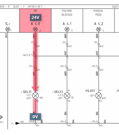
PLC DIGITAL OUTPUT CARD DIAGRAM
FAQ
What is SLD in electrical?
A single-line diagram (also known as an SLD or one-line diagram) is a simplified representation of an electrical system. Symbols and lines are used to represent the nodes and connections in the system and electrical characteristics may be included as well.
What is SLD vs LD?
One-line diagrams or single-line diagrams are used in electric power systems (including distribution systems); these are usually three-phase. Ladder diagrams are used in control circuits of an industry and its machinery, using relays. It is the programming language used in PLCs.
What are 3 line drawings?
Three-line diagrams show all three phases in three-phase applications. It is the detailed representation of AC flow from source to bus to CT to end device. Both AC and AC voltage three-phase circuits may be represented using this diagram.

Fathima Sadina works as a Technical Associate at IIPD, where she dives into the world of Industrial Automation, focusing on PLC, SCADA, and VFD systems. With a keen passion for spreading know-how, she loves to craft engaging blog posts on a wide array of technical subjects.