What programming methods are used in PLC? Delving into the realm of industrial automation, the choice of programming methods in PLC (Programmable Logic Controller) is pivotal. These methods intricately define the functionality, shaping the backbone of efficient and effective control systems. It’s crucial to navigate this landscape wisely for optimal automation performance.
Introduction
In the realm of industrial automation, Programmable Logic Controllers (PLCs) serve as the backbone, ensuring seamless control of machinery and processes. Understanding the diverse programming methods used in PLCs is essential for engineers and automation professionals looking to optimize their systems.
PLC Programming Languages
PLCs employ different programming languages to execute specific tasks and achieve precise control over automation processes. Let’s delve into the primary programming languages utilized in PLC programming:
- Ladder Logic
- Function Block Diagram
- Structured Text
- Sequential Function Chart
- Instruction List
- Continuous Flow Chart
Traditional Programming Methods
Traditional Programming Methods in PLC, including Ladder Logic and Functional Block Diagrams, form the foundation of control systems.
These methods employ graphical representations to simplify complex processes. In the detailed discussion below, we explore how these time-tested approaches contribute to the efficiency and clarity of PLC programming.
1. Ladder Logic (LD):
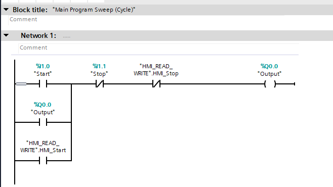
Ladder Logic is one of the most widely used languages in PLC programming. It resembles electrical relay logic diagrams, making it intuitive for electricians and technicians. LD utilizes graphical symbols such as contacts, coils, timers, and counters interconnected by rungs to create logic instructions. It excels in implementing sequential control and mimics the traditional relay-based control circuits.
Elements Used In Ladder Logic Programming
In Ladder Logic, you create programs using graphical elements called “rungs.” Each rung represents a specific logical operation or control function. Here are some basic elements and concepts commonly used in Ladder Logic:
Contacts and Coils:
- Contacts: Represent input conditions, such as sensors or switches. They can be normally open (NO) or normally closed (NC).
- Coils: Represent output devices, like motors or solenoids. When the conditions specified by the contacts are met, the coil is energized.
Timers:
- TON (Timer On Delay): Delays the activation of the output coil for a specified time after the input condition is met.
- TOF (Timer Off Delay): Delays the deactivation of the output coil for a specified time after the input condition is no longer met.
Counters:
- CTU (Count Up): Counts the number of input conditions that occur.
- CTD (Count Down): Counts down a preset number of occurrences before triggering an output.
Comparators:
- Equal (==): Checks if two values are equal.
- Not Equal (!=): Checks if two values are not equal.
- Greater Than (>): Checks if one value is greater than another.
- Less Than (<): Checks if one value is less than another.
Math Operations:
- Basic arithmetic operations like addition (+), subtraction (-), multiplication (*), and division (/) can be used to manipulate values in Ladder Logic.
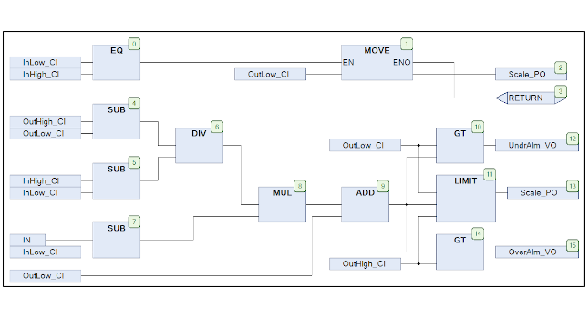
2. Function Block Diagram (FBD):
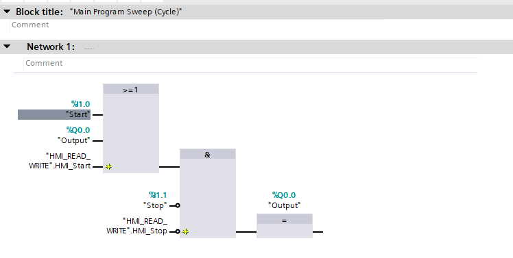
Function Block Diagram is another graphical programming language in PLCs. FBD represents functions, operations, and processes through interconnected blocks, each performing specific operations. It allows for modularity and reusability of code, making it efficient for complex control tasks.
In an FBD, each block typically represents a specific function or operation, and the connections between blocks show the flow of data or control signals between them. The blocks can be simple functions, such as arithmetic operations or logical comparisons, or more complex functions like control loops or input/output operations.
Function blocks can be interconnected to create a visual representation of the entire system or process, allowing engineers and programmers to design, analyze, and troubleshoot complex systems more efficiently. FBDs are commonly used in industries such as manufacturing, process control, and automation, where complex control systems need to be implemented.
3. Structured Text (ST):
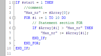
Structured Text (ST) is a high-level programming language used in industrial automation and control systems, especially in programmable logic controllers (PLCs). It is designed for developing control logic for real-time applications in a structured and readable format. ST is often used in conjunction with the IEC 61131-3 standard for PLC programming.
Structured Text (ST Code Sample)
PROGRAM MainProgram
VAR
    temperature: REAL := 25.0;  // Variable to store temperature
    setpoint: REAL := 20.0;    // Desired temperature setpoint
    output: REAL;              // Output variable

    // Constants
    GAIN: REAL := 0.5;         // Proportional gain

END_VAR

// Main control logic
IF temperature > setpoint THEN
    output := GAIN * (temperature - setpoint);
ELSE
    output := 0.0;
END_IF

// Additional logic or actions can be added here

END_PROGRAM
4. Sequential Function Chart (SFC):
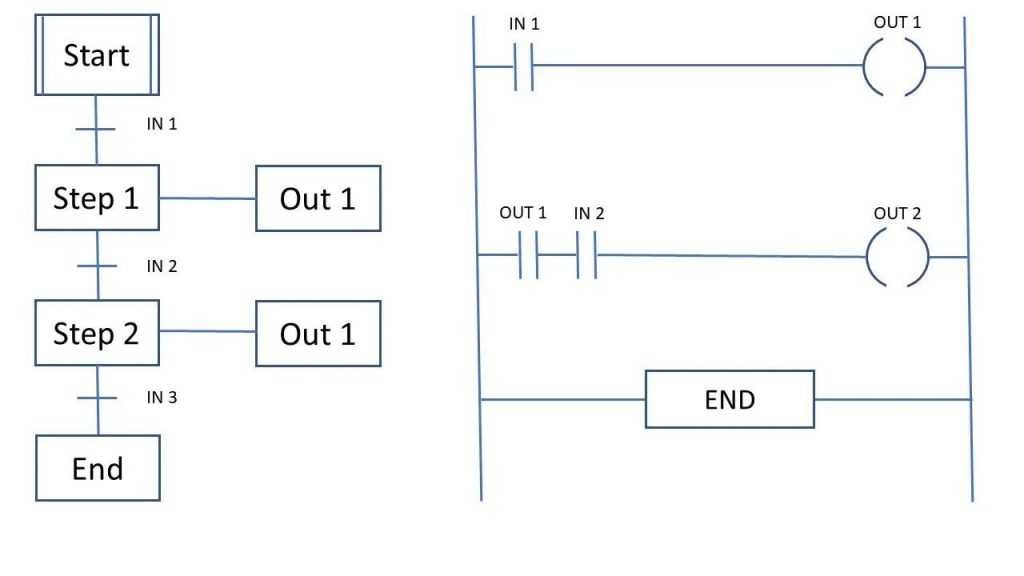
Sequential Function Chart is a graphical language focusing on the flow of control in PLC programs. It divides the program into steps, transitions, and actions represented by interconnected blocks. SFC is excellent for designing complex state-based control systems and sequential processes.
Here are the key elements and concepts associated with Sequential Function Charts:
- Steps:
- Steps represent individual actions or operations in a control process. They are depicted as rectangles and contain the specific task or function to be performed.
- Transitions:
- Transitions are represented by arrows and define the sequence in which steps are executed. Transitions connect steps and indicate the conditions under which the control flow moves from one step to another.
- States:
- States are used to group related steps together. They are represented by dashed rectangles and help organize the control logic into manageable sections. A state may contain multiple steps and transitions.
- Initial and Final Steps:
- Each SFC typically begins with an initial step, indicating the starting point of the control process. The chart concludes with a final step, denoting the end of the sequence.
- Actions and Conditions:
- Steps can include both actions (tasks to be performed) and conditions (logical conditions that must be satisfied for the transition to occur). Conditions are often associated with specific input or output values.
- Parallel Branches:
- SFC allows the representation of parallel branches, enabling the simultaneous execution of multiple steps or sequences. This is particularly useful for modeling concurrent processes in a control system.
- Step and Transition Labels:
- Steps and transitions may have labels to provide additional information or describe the purpose of a particular element in the control logic.
SFCs are powerful tools for designing and documenting control systems, making it easier for engineers and programmers to understand, analyze, and modify complex sequences of operations. They provide a visual representation of the control logic, aiding in troubleshooting, maintenance, and system comprehension.
5. Instruction List (IL):
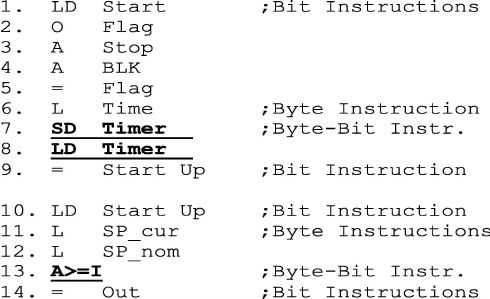
Instruction List (IL) is one of the programming languages used in Programmable Logic Controllers (PLCs). A PLC is a digital computer used in industrial automation to control and monitor different processes and machinery. The Instruction List is a low-level programming language that represents a set of instructions written in a symbolic format.
In Instruction List programming, each line of code typically represents a single instruction or operation that the PLC will execute. These instructions are written using mnemonic codes and operands. The structure is similar to assembly language, making it more machine-oriented and closer to the hardware.
Here is a simple example of an Instruction List program:
LD      I:1/0      ; Load input I:1/0 (address of a digital input)
AND     I:1/1      ; AND with input I:1/1
OUT     O:2/2      ; Output the result to output O:2/2
In this example:
LDis the mnemonic for Load.ANDis the mnemonic for AND.OUTis the mnemonic for Output.
The operands like I:1/0, I:1/1, and O:2/2 represent specific addresses in the PLC’s memory where inputs and outputs are located.
Instruction List is just one of several programming languages used in PLC programming, and its popularity may vary depending on the manufacturer and application requirements. It offers a simple and concise way to represent control logic in a PLC and is often used for basic to intermediate control tasks.
6. Continuous Function Chart (CFC):
Continuous Function Chart is a graphical language similar to FBD but emphasizes continuous processes and mathematical functions. It’s beneficial in applications where continuous mathematical calculations and control algorithms are prominent.
Choosing the Right Language:
The selection of programming language in PLCs depends on the application requirements, complexity, familiarity of the programming team, and efficiency considerations. For instance, Ladder Logic might suit simple sequential control, while Structured Text might be preferable for complex mathematical computations.
In conclusion, the diverse array of programming languages available in PLCs offers flexibility and adaptability to engineers and programmers, catering to the specific needs of industrial automation across various industries.
Understanding these languages empowers PLC programmers to craft efficient, reliable, and scalable control systems, advancing the landscape of industrial automation.
FAQs
What are the methods to program a PLC?
PLCs employ different programming languages to execute specific tasks and achieve precise control over automation processes. There are 5 main methods to Program PLC using programming languages such as,
1. Ladder Logic
2. Function Block Diagram
3. Structured Text
4. Sequential Function Chart
5. Instruction List
What are the 4 main parts/components of a PLC?
The 4 main components of a PLC are
1. Input/Output Modules
2. Processor – CPU and Memory- Program/Data
3. Power Supply
4. Communication Ports – for programming and communication with other PLCs
What is an HMI in PLC?
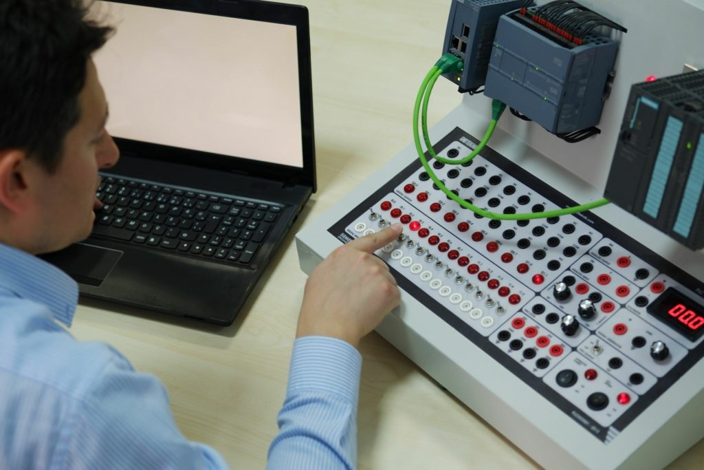
A Human Machine Interface (HMI) is a user interface that allows interaction between an operator and a machine, system, or process in industrial automation. It displays real-time data, controls equipment, and provides a platform for monitoring and managing operations. HMIs incorporate visual elements like graphics, buttons, and indicators, enabling users to monitor processes, input commands, and receive feedback, enhancing efficiency and control in industrial settings.
Which PLC is best for beginners?
Choosing the “easiest” PLC brand for beginners often depends on various factors such as personal preferences, available training resources, industry standards, and the level of support provided by the manufacturer. However, Siemens and Allen-Bradley often stand out due to their widespread use, extensive resources, and user-friendly programming software.
Siemens PLCs (Simatic S7 series):
Siemens is widely used globally, offering a range of PLCs suitable for different industries and applications.
The programming software, TIA Portal (Totally Integrated Automation), provides a user-friendly interface for programming various Siemens PLCs.
It offers excellent documentation, tutorials, and online resources for beginners to learn and troubleshoot.
Allen-Bradley (Rockwell Automation):
Allen-Bradley PLCs, especially the Micro800 and CompactLogix series, are prevalent in many industries.
They offer software like Studio 5000 and Connected Components Workbench that provide an intuitive environment for programming.
Rockwell Automation provides extensive training resources, support forums, and a wide user base for guidance.
Mitsubishi Electric PLCs:
Mitsubishi PLCs, including the MELSEC series, are popular in industrial automation.
The GX Works software offers a user-friendly interface, and its simulation tools aid beginners in understanding programming concepts.
Mitsubishi provides comprehensive documentation and training materials for novice programmers.
Omron PLCs:
Omron PLCs, such as the CP1 and NJ series, are known for their reliability and ease of use.
The CX-One software package simplifies programming with its user-friendly interface and extensive libraries.
Omron offers training courses and support to help beginners grasp programming concepts.
Schneider Electric (Modicon and Unity):
Schneider Electric’s PLCs, including the Modicon M340 and M580 series, are widely used in various industries.
The Unity Pro programming software provides an easy-to-understand environment for beginners.
Schneider Electric offers training sessions and online resources for beginners to get started.
Ultimately, beginners should consider factors like availability of training, community support, ease of programming software, and the specific requirements of their industry when choosing a PLC brand to start their learning journey in industrial automation.
Is PLC easy to troubleshoot?
As an automation expert, I can attest that while Programmable Logic Controllers (PLCs) are designed to facilitate industrial control and automation, troubleshooting them can vary in complexity based on multiple factors.
PLCs are generally reliable, but troubleshooting can pose challenges due to:
Complexity of Systems: Industrial setups can involve intricate machinery and processes. When an issue arises, identifying the root cause within this complexity can be challenging.
Variety of Applications: PLCs are used in diverse industries with varying requirements. Troubleshooting may require specialized knowledge of the particular application and its associated hardware.
Programming Errors: Mistakes in programming logic can cause unexpected behavior. Identifying and rectifying these errors may demand a comprehensive understanding of the programmed logic.
Interfacing with External Devices: PLCs interact with numerous devices such as sensors, actuators, and HMIs. Troubleshooting may involve diagnosing problems in these interconnected components.
However, with the right expertise, tools, and approach, PLC troubleshooting can be streamlined:
Comprehensive Documentation: Detailed documentation of the control system, including program logic, wiring diagrams, and manuals, can expedite troubleshooting.
Diagnostic Tools: Modern PLCs offer diagnostic capabilities, such as error logs, real-time monitoring, and simulation modes, aiding in pinpointing issues.
Experience and Training: Skilled technicians and engineers with training and experience in PLC troubleshooting can swiftly identify and rectify problems.
Systematic Approach: Following a structured methodology, such as dividing the system into segments and testing each part, helps isolate and solve issues systematically.
Collaboration and Support: Utilizing available resources like online forums, technical support, and collaborating with colleagues can offer additional insights and solutions.
In essence, while troubleshooting PLCs might not always be straightforward due to the complexities involved, a combination of knowledge, resources, and a methodical approach significantly eases the process. The ability to systematically diagnose and resolve issues is crucial for maintaining efficient industrial automation systems.
Can I learn PLC on my own?
Yes, it’s entirely possible to learn Programmable Logic Controllers (PLCs) on your own, especially with the vast array of resources available today. Learning PLCs independently requires dedication, access to relevant materials, and a structured approach. Here’s a guide on how you can go about it:
Start with Basics:
Familiarize yourself with the fundamentals of PLCs, including their purpose, components, and how they operate in industrial automation.
Acquire Learning Materials:
Utilize online resources, such as tutorials, eBooks, and educational websites that offer introductory PLC courses.
Look for reputable sources that provide hands-on exercises, simulations, or programming software to practice.
Select a PLC Platform:
Choose a specific brand or model of PLC to focus on. Popular manufacturers include Siemens, Allen-Bradley (Rockwell Automation), Mitsubishi, etc.
Obtain simulation software or a low-cost PLC trainer kit to practice programming and get hands-on experience.
Learn Programming Languages:
Start with Ladder Logic (LL) as it’s the most commonly used programming language in PLCs and relatively easier to understand for beginners.
Progress to other languages like Structured Text (ST), Function Block Diagram (FBD), Instruction List (IL), and Sequential Function Chart (SFC) as you advance.
Practice and Experiment:
Create simple projects or scenarios to apply what you’ve learned. Start with basic circuits, then move on to more complex tasks as you gain confidence.
Experiment with different sensors, actuators, and input/output modules to understand their interactions with the PLC.
Online Communities and Forums:
Join forums, discussion boards, or online communities dedicated to PLC programming. Engaging with others, asking questions, and sharing experiences can provide valuable insights and support.
Continual Learning and Advancement:
Stay updated with the latest advancements in PLC technology, industry standards, and best practices through online courses, webinars, and industry publications.
Seek Practical Experience:
If possible, try to get hands-on experience through internships, projects, or entry-level positions in industries that use PLCs. Practical exposure complements theoretical knowledge.
Remember, learning PLCs on your own requires dedication and consistent effort. Patience is key as mastering these skills takes time. With the right resources, persistence, and a passion for learning, you can indeed become proficient in PLC programming independently.
Where is the best place to learn PLC programming, and can I find resources for various PLC brands?
If you’re looking for a comprehensive and hands-on approach to learning PLC programming for various brands, the Institute of Innovation and Professional Development (IIPD) is an excellent choice. They offer specialized courses covering PLCs from major manufacturers like Siemens, Allen-Bradley, Omron, Mitsubishi, and more.
Moreover, many PLC manufacturers provide online learning resources through their official channels. Siemens, for instance, offers tutorials and documentation through their official website. Rockwell Automation, the parent company of Allen-Bradley, provides extensive training resources online through its official platform.
So, whether you prefer structured courses from IIPD to cover a broad spectrum of PLC brands or opt for manufacturer-specific learning from official sources, there are ample opportunities to enhance your PLC programming skills.

Senior Tech Manager at IIPD Global, weaving magic in Industrial, Building, and home Automation. KNX Tutor on a mission! Embracing Industry 4.0 and proudly shaping the tech landscape. Certified by CertNexus to ignite minds!